Month: June 2017

Get an Intuitive Feel for Gas Properties with this Simulator

Today I want to bring attention to the PhET Gas Properties Simulator. This is a wonderful tool that allows a learner to interact with all of the levers in a gas system. The tool is set up so that the learner can add gas particles into a chamber and then see the results as the system’s parameters (temperature, volume, etc.) are changed.

In the figure below, I introduced equal amounts of a heavy gas and a light gas (60 of each) and then opened the lid on the top of the chamber a bit to see what happens. After letting the simulation run for a short while I could see that the light gas was escaping faster than the heavier gas, the temperature was dropping in the system along with the pressure.

Capture PhET1.PNG

60 heavy gas molecules and 60 light gas molecules were introduced into the chamber. The lid was cracked open and gas was allowed to escape. At the time of the screen shot, 55 heavy gas molecules and 50 light molecules remained in the chamber.

There are also some graphs that give insight of the molecular speeds and energies of the molecules. Lessons and exercises are available on the PhET website.

As a vacuum technologist, I think in terms of molecular flow where the molecules interact with the walls of a conduit rather than collide with each other. When opening the lid to allow that gas to expand out into space, it occurred to me that this is also a good tool to help convey the idea that in order for a pump to remove a gas molecule from a chamber, the molecule has to enter the pump’s inlet. Since the lid has a variable aperture, it can be use to introduce the concept of how a high vacuum pump’s pump speed is dependent on the inlet diameter .

The Gas Properties Simulator is suitable for high school, college, and continuing education students. I have loaded it onto my work laptop and will be using this in my corporate vacuum lectures in the future. I hope you will find it useful too.

Understanding Modern Vacuum Technology discusses the gas properties that can be explored with this simulator. UMVT also discusses vacuum pumps and pressure measurement.

Cryopumps for Executives and other Layfolk

I was once asked by my corporate executives to explain how cryopumps work with the orders, “Keep the physics out of it, Steve.”

“Hmmm…”, I thought to myself, “How the devil and I going to do that?” And there was

Capture.PNG

Cryopump figure from US6263679

the challenge. When dealing with the top executives, you don’t want to start the lecture with, “First there was a Big Bang…” and then talk about the history of the universe and how that lead to cryopumps. The executives were facing some technology challenges and they needed to understand actually what cryopumps are, what they do and why use a cryopump instead of a turbomolecular pump.

Then I realized that I although my execs are highly skilled engineers, they do not live and breathe vacuum technology day in and day out like I do. After all, that is why I am on the payroll, so they don’t have to put attention on the vacuum equipment. This post was inspired by the presentation that I put together for my execs, “Cryopumps for Layfolk”

frosty.JPG

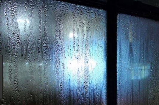
We all have had the observation that frost and ice forms on a cold surface. Most of us were born after the advent of the frost-free refrigerators. Those of us who were not can remember the times when mom and dad had to defrost the freezer in the middle of summer when high humidity condensed and froze on the walls of the freezer. (I am in that latter mix.)

You may ask, “What does this has to do with vacuum technology?” That is a fair question.

Consider a closed chamber with a fixed amount air inside. That air exerts a pressure on the inside surface of the chamber.

frost.JPG

Now let’s make the chamber wall so cool that the gas freezes on the side of the wall. Molecules that are taken out of the gas phase and made into a solid phase no longer contribute to the chamber pressure. Mr Freeze.JPG

This is the basic principle of cryopumping, use cold surfaces to capture molecules that are in a gaseous state so they do not contribute to the pressure in the chamber. There are three methods of capture.

The first method of capture is condensation, the process in which a gas changes state into a liquid, usually when it comes in contact with a cold surface. This is an excellent method of dehumidifying a room in the hot summer, but it is not very useful in high vacuum systems. Depending on the temperature, the liquid can easily revert back into a gaseous state and the pressure will remain relatively high.

condensation.JPG

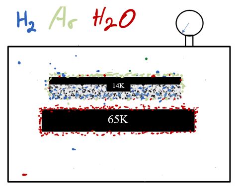
In the chamber below we have a mixture of gases, hydrogen, Argon and water vapor. The total pressure in the chamber is a sum of the partial pressures of each of the gases. I have chosen these three gases because they are each captured differently in a cryopump, as you will see.

Capture1.JPG

Now let’s put a cold surface in the system at 35ºF. This is cold enough to condense the water vapor, but the liquid water is still fairly mobile and will tend to drip in the chamber. We may expect a slight decrease in pressure. However the dripping in the chamber is not acceptable.Capture2.JPG

frosted.JPG

The second method is to capture gas with very cold surfaces. This is known as cryosorption. When a gas molecule strikes a cold surface and remains, it gives up heat to the surface. It can remain in solid form if the temperature is below the freezing point of the gas at the system pressure. This depends on temperature and pressure. 

The way to capture gas and have it remain is to keep the surface temperature well below the freezing temperature of the gas.

Let’s take our system and put a cold surface in that is well below the freezing point of water at the desired pressure. Here we have the surface chilled to 65K. At that temperature, nearly all of the water in the chamber that strikes the 65K surface will remain in solid form, thus it is no longer able to contribute to the pressure in the chamber and the pressure drops accordingly. A surface at 65K is cold enough to pump water vapor and many hydrocarbons.

Capture3.JPG

The 65K surface is not cold enough to cryosorb H2 or Ar, so they will remain in a gaseous state. Some of the H2 and Ar may become trapped in the water ice, however a more efficient way to pump H2 and Ar is to put another surface into the chamber chilled to 14K.


Capture4.JPG

The 14K surface is cold enough to freeze out the argon. It will also capture N2, CO, CO2, Kr, O2 and other such condensable  gases. This leaves the non-condensable gases such as H2, He and Ne.

In our system, we still have the H2 gas remaining. There is a third cryopumping mechanism that is employed, cryotrapping. This method of pumping is done by taking a porous substance and chilling it down to a cryogenic temperature. When a gas molecule lands on the surface inside one of the pores, it will give up it thermal energy and reside there for an extended period of time. The colder the substance, the longer the gas will stay on the surface. In the days before dry roughing pumps, canisters of Zeolite were chilled in liquid nitrogen. The gas would then be cryotrapped in the high surface area Zeolite.

Another material is coconut charcoal. This has a high surface area and is extremely porous. Charcoal is typically cooled to between 9K and 15K for the purpose of cryotrapping H2. Capture5.JPG

As the charcoal becomes saturated with H2, the ability of the charcoal to pump H2 will diminish. In order to rejuvenate the pump speed, the charcoal is warmed up and the hydrogen is liberated.

Now lets add a layer of porous charcoal on the 14K surface. Now we have a means to pump every gas that will be found in a vacuum system and the pressure drops accordingly.

Capture6.JPG

Now that we know how to pump gases with cryogenic surfaces, we can take a look at the application of these methods.

Capture7.PNGThe construction of a cryopump is built around the cold-head cylinder. Inside the cylinder is a reciprocating “displacer” which is like a hollow piston which compressed helium is allowed to expand. There is a whole thermodynamic refrigeration cycle associated with this that is beyond the scope of this piece. I do have it explained in detail in the book Understanding Modern Vacuum Technology.

The figure to the left is from UMVT pg 206. Inside the cryopump, mounted to the refrigerator is the radiation shield. This surface is kept at 80K in this illustration and is set anywhere from 65K to 100K depending on the cryopump model. In my descriptions above, I used 65K to match our process requirements.

The radiation shield at 80K is thermally connected to the inlet 80K condensing array. Inside the pump, the top of the refrigerator is a cold stage that operates at 14K. An array containing bare surfaces and surfaces covered with charcoal is affixed to the 14K stage. Now let’s see how it all works together.

Capture8.PNG

The cryopump is attached to a chamber. Water vapor in the chamber strikes the 80K frontal array and is cryosorbed onto the surface. Gases that do not cryosorb at 80K are allowed to enter into the pump. Gases such as Ar, N2, O2, etc. are cryosorbed onto the 14K surfaces and the He, Ne and H2 are cryotrapped in the charcoal. In most cryopumps, the charcoal is protected such that the condensable gases will strike a bare surface first, leaving the charcoal relatively free for trapping the non-condensable gases.Capture9.PNG

This particular design of a cryopump is used where there isn’t an appreciable amount of H2 in the chamber. It is easier for gases to strike the bare 14K surface first, which means the H2 has to make several collisions inside the pump before it becomes cryotrapped. This may reduce the H2 pump speed, which a compromise for this arrangement.

You may ask, “Why not just make everything 14K and be done with it?” There are two stages where arrays are attached to the cryopump refrigerator. The 80K stage (known as the first stage) can handle much higher amounts of the heat, 45 watts is a typical value. The 14K stage (know as the 2nd stage) can only handle on the order of 8 watts. Thus the 80K stage is used to handle the heat load from the external pump walls and the 14K stage only sees a 66K temperature difference rather than a 270K difference from the room temperature vacuum vessel wall.

There are many safety protocols that must be followed. Cryopumps are “capture” pumps, meaning that they store the gas pumped rather than compressing and exhausting it as in the cases of turbomolecular pumps and mechanical roughing pumps. Once the cryopump reaches capacity for a gas, the pump speed suffers. At that point the cryopump must be “regenerated” The pump is allowed to warm up and the gas is liberated. Unless the gas can escape, it can reach extremely high pressures at room temperature. In order to prevent the vacuum vessel from rupturing and creating a safety hazard, the gas is allowed to exhaust through a poppet valve that opens at just above atmospheric pressure.

Since a great deal of gas can be stored in the pump, proper safety precautions must be followed so that the ambient air is still breathable in the lab or reactive byproducts do not cause other hazardous conditions. Be sure to read and follow all safety information in the pump’s manual.

Finally, I have talked a great deal about pumping H2 with cryopumps. Processes involving H2 can create explosive conditions and there are a set of safety protocols specifically for H2. Of particular danger are the processes that produce ozone. Ozone is very reactive in cryopumps during the regeneration process. I bring this points up not to scare you away from cryopumps, I just want you to be aware.

I hope that you found this little primer helpful if you have not been exposed to cryopump technology before. In Understanding Modern Vacuum Technology, you will find a wealth of information about cryopumps, a detailed description of the closed loop helium refrigerator and information about cryopump safety.


Take a close look at the construction of the Edwards GXS Screw Roughing pump

In this video, we get a close look at the construction and design considerations of an Edwards GXS screw pump with a Roots Booster. While watching this video, I am reminded that vacuum technology is a multi-disciplinary activity. These pumps are the result of mechanical engineers, electrical engineers and vacuum scientists.

I hope this video is helpful.

You can find the basics of roughing pump technology in Understanding Modern Vacuum Technology. Just click on the link in the right banner which will take you to Amazon.com.

Measuring High Vacuum Pressure with Goal Posts

BAG.gif

Most vacuum technologist are familiar with the construction of a Bayard-Alpert gauge. A filament  emits electrons that are accelerated into a grid where ions are formed. Ions striking the collector cause a current to flow through an ammeter which is proportional to the pressure inside the gauge.

Back in the 1990s, Granville-Phillips embarked on a project to create an inexpensive OEM gauge for the semiconductor market. We had just finished the development of the Stabil-Ion® gauge. The Stabil-Ion was designed to be an extremely stable and reproducible gauge (Arnold et. al. 1994) to serve customers with the demanding vacuum requirements. We learned many techniques to make a gauge stable and reproducible, but it was not attractive to the OEM market because of the price.

Stabil-Ion-3D-illustration_GS.png

Granville-Phillips Stabil-Ion gauge. (Arnold et. al. 1994.)

We turned out attention to a lower cost, compact gauge that could be offered at a lower price. One of the problems with all compact gauges is that volume inside the grid where the ions are formed is much smaller than a conventional B-A gauge. This means that the number of ions that are formed in the region where they can be collected is greatly reduce. So it is important that we collect as many ions as possible.

Inside a B-A gauge grid, ions  formed with certain angular momentum values cannot be collected because they form stable orbits around the collector as shown below.

precessing ion.gif

A dual collector design was introduced to solve that problem. Since the grid is at 180 volts and the collector is at 0 volts the electric field well has as saddle shape. The analogy would be like trying to place a basketball on the back of a horse. It will try to fall off either side of the horse rather than staying on its back.

MicroIo ion paths.gif

Ions formed on on the saddle shaped potential field are driven towards the the collectors. (Understanding Modern Vacuum Technology, pg. 101. Courtesy of MKS Instruments, Inc.) 

MicroIon Patent image

Cutaway drawing of a Granville-Phillips MicroIon® gauge. The dual collectors are labeled 140a and 140b. (Knott 2008)

The result of this design was that the sensitivity for this gauge is 3 to 4 times the other gauges in its class.

You can lean more about Bayard-Alpert gauges and other vacuum metrology devices by reading Understanding Modern Vacuum Technology. 

Arnold, Bills, Borenstein and Borichevsky (1994) J. Vac. Sci. Technol. A, 12, 568

Knott (2008) Patent No. US 7,456,634 B2

MicroIon and Stabil-Ion are registered trade marks of MKS Instruments, Inc.

AVS Symposium in Tampa

tampa.jpg

Join me in Tampa for the AVS 64th International Symposium and Exhibition. The session schedule has been drafted out and I’ve had a first look at it. I will be co-moderating the the Monday morning Vacuum Technology Division session VT-MoM. The focus topic is Process with Measurement in Vacuum. There will be presenters from NIST to discuss the cutting edge pressure measurement technologies, an invited talk ROSINA/ROSETTA: Exploring the Origin of our Solar System with Mass Spectrometry in Space by Katherin Altwegg, University of Bern and several other contributed talks.

The Vacuum Technology Division (VTD) provides a forum for research in achieving, maintaining, analyzing, and measuring vacuum across a wide range of pressures and applications.

VTD will again host the “Ask the Experts” booth, located in the exhibit area, where experienced vacuum scientists, engineers and technicians strive to answer perplexing vacuum technology questions.

Be sure to watch the AVS website for updates.


Remembering D-Day, Tide Prediction

I bumped into a great historical article about the history of predicting tides and the role that tides played in the planning of D-Day. You can find The tide predictions for D-Day on the Physics Today website.

It is interesting on many levels; the history of tide predictions, the development of tide tables, the evolution of computers to predict tides and the historical view of how the tides are formed.

D-Day.JPG

A LCVP (Landing Craft, Vehicle, Personnel) from the U.S. Coast Guard-manned USS Samuel Chase disembarks troops of Company E, 16th Infantry, 1st Infantry Division (the Big Red One) wading onto the Fox Green section of Omaha Beach (Calvados, Basse-Normandie, France) on the morning of June 6, 1944. American soldiers encountered the newly formed German 352nd Division when landing. During the initial landing two-thirds of Company E became casualties. Wikipedia.org

While reading the article, I was reminded of YouTuber The Engineer Guy’s 8 video set of a harmonic analyzer that is similar to the machined described in the Physics Today piece.


What you should know about water pumps in vacuum chambers

It is well known that water vapor in a vacuum chamber presents a unique challenge because of the polar nature of the water molecule. Water likes to stick to surfaces and reside there until it desorbes, only to stick to another surface. This is why the predominant gas load in a chamber at high vacuum pressure (which is approximately between 1×10⁻³ and 5×10⁻⁸ torr)  is water vapor.

As one pumps a chamber full of atmospheric gas, gases such as Ar, N2 and O2 are quickly removed. As this happens, the composition of the gas becomes predominately water vapor.

In a production environment, this water partial pressure can lengthen the time it takes to get into production after the chamber has been opened. In a semiconductor fab, where time is money, the faster you get back into production, the faster you can start making product (money).

Benefit may be realized by using cryogenic surfaces that provide auxiliary water vapor pumping. These “water pumps” come in many different forms such as cooled tubes or panels within the system or cryo-cooled baffles in front of other HiVac pumps. The cooling can accomplished with the use of liquid nitrogen or closed loop refrigeration.

The water pumping speed of a cryogenic surface is dependent on the temperature of the surface and the surface area of the cryogenic surface.

cryosurface pump speed.PNG

Water vapor pumping speed of cryogenic surfaces at constant surface temperature. Lafferty, 1998 ISBN 0-471-17593-5

Below are two different styles of water pumps that can be placed on the inlet stage of a high vacuum pump such as a turbomolecular pump or a diffusion pump.

EtchWP2_400.jpg LowProfileWaterpump_400.jpg

Two styles of water pumps from Brooks Automation.

Some thought must be used when deciding what type of water pump to use and how to use them.

In chambers that will capture water vapor on a cyclical basis such as a load lock, a considerable amount of frost can build up over time. This frost must be eventually regenerated (sublimated off to rejuvenate the pumping surface). Care must be take while this is done. If the ice is just allowed to melt, it will drip on the chamber floor. This can cause corrosion and particles in sensitive applications.

One method to prevent this is to bring the temperature of the surface up to a moderate temperature and allow the gas to sublimate while under rough vacuum. This can be a lengthy process.

An alternative method is to purge the the chamber with a flow of N2, which may not be practical if the chamber is large.

In critical applications, the water pumping surface is often affixed to the chamber with its own chamber that can be valved off. This can limit the pump speed of the water pump but at least the regeneration can be done as with a cryopump.

Another design consideration is whether or not the water pump can function with the process. For example, having a surface with frost in the same chamber as a plasma process is not workable.

Since we are interested in removing water and what the effect on the system pressure will be, let us break Ptot into two components; PH2O, the partial pressure of water and Pr, the remaining gas that is not water vapor.

pressure.PNG

Where Qx is the gas load and Sx is the pump speed for each water vapor and residual gases. Quite often one knows the gas load QH2O of the water vapor from a residual gas analysis. Using that one can work out the expected water vapor pump speed and a prediction can be made has to how much the total pressure can be reduced.

In the case when a water pump is used as an appendage pump, meaning that it can be isolated by a gate valve, one must be aware that if there is a partial pressure of water vapor in the system and if the pump is isolated then the water pump speed reduced. The pressure of the system will increase accordingly. For example, suppose there are a cryopanel and a turbomolecular pump in parallel on the chamber the total pump speed for water will be

pump speeds.PNG

If one isolates the cryopanel, then one is only left with turbomolecular pump pumping on that water vapor. At the time that the cryopanel is isolated, there is a water vapor gas load at that particular time is H2O(t). Therefore the resulting pressure will rise accordingly depending on how much cryopanel water pump speed is loss.

This is important to understand, especially if the system engineer is interested in reducing the post maintenance recovery of a tool using water pumps. Many tools such as plasma systems cannot tolerate a water pump in the process environment therefore the water pump is put behind an isolation gate valve. The process engineer must understand that although the target recovery pressure may have been achieved with the use of a water pump that there is still a water gas load, H2O(t). The water pumping speed SH2O will be reduced to the level of the high vacuum pump and PH2O will increase according to the loss of water pump speed.

I hope that you find this helpful. More useful vacuum technology can be found in the book Understanding Modern Vacuum Technology.

What is a Watt Balance?

These are “exciting” times for meteorologist. In 2018, it is expected that all of the fundamental SI units will be defined, including the kilogram. Right now, a kilogram artifact sits in France. It is the kilogram which is agreed that will be the definition of the kilogram, period. So if it shifts by a microgram, the reference standards in the national laboratories will shift by a microgram. Wouldn’t it be better to have a definition of the kilogram based on fundamental constants of the universe rather than an artifact? That is what is going on right now.

First, take a look at this short video that describes a watt balance is and how it works. This will help you understand the video that follows.

watt balance diagram

And of course, there has to be some vacuum technology involved!

Watt Balance.PNG chamber.PNG

The NIST-4 watt balance has measured Planck’s constant to within 34 parts per billion, demonstrating that the high-tech scale is accurate enough to assist with 2018’s planned redefinition of the kilogram. The watt balance is shown sitting in the bottom half of its vacuum chamber (left) and with the vacuum dome installed (right).

Credit: J. L. Lee / NIST

YouTuber Veritasium takes us into the National Institute of Standards and Technology to see one of the American standards.


You can learn much more at the NIST Physical Measurement Laboratory site.
NIST CODATA 2010 wallet card.jpg

NIST CODATA 2010 wallet card 2.jpg