Uncategorized

Take a close look at the construction of the Edwards GXS Screw Roughing pump

In this video, we get a close look at the construction and design considerations of an Edwards GXS screw pump with a Roots Booster. While watching this video, I am reminded that vacuum technology is a multi-disciplinary activity. These pumps are the result of mechanical engineers, electrical engineers and vacuum scientists.

I hope this video is helpful.

You can find the basics of roughing pump technology in Understanding Modern Vacuum Technology. Just click on the link in the right banner which will take you to Amazon.com.

Measuring High Vacuum Pressure with Goal Posts

BAG.gif

Most vacuum technologist are familiar with the construction of a Bayard-Alpert gauge. A filament  emits electrons that are accelerated into a grid where ions are formed. Ions striking the collector cause a current to flow through an ammeter which is proportional to the pressure inside the gauge.

Back in the 1990s, Granville-Phillips embarked on a project to create an inexpensive OEM gauge for the semiconductor market. We had just finished the development of the Stabil-Ion® gauge. The Stabil-Ion was designed to be an extremely stable and reproducible gauge (Arnold et. al. 1994) to serve customers with the demanding vacuum requirements. We learned many techniques to make a gauge stable and reproducible, but it was not attractive to the OEM market because of the price.

Stabil-Ion-3D-illustration_GS.png

Granville-Phillips Stabil-Ion gauge. (Arnold et. al. 1994.)

We turned out attention to a lower cost, compact gauge that could be offered at a lower price. One of the problems with all compact gauges is that volume inside the grid where the ions are formed is much smaller than a conventional B-A gauge. This means that the number of ions that are formed in the region where they can be collected is greatly reduce. So it is important that we collect as many ions as possible.

Inside a B-A gauge grid, ions  formed with certain angular momentum values cannot be collected because they form stable orbits around the collector as shown below.

precessing ion.gif

A dual collector design was introduced to solve that problem. Since the grid is at 180 volts and the collector is at 0 volts the electric field well has as saddle shape. The analogy would be like trying to place a basketball on the back of a horse. It will try to fall off either side of the horse rather than staying on its back.

MicroIo ion paths.gif

Ions formed on on the saddle shaped potential field are driven towards the the collectors. (Understanding Modern Vacuum Technology, pg. 101. Courtesy of MKS Instruments, Inc.) 

MicroIon Patent image

Cutaway drawing of a Granville-Phillips MicroIon® gauge. The dual collectors are labeled 140a and 140b. (Knott 2008)

The result of this design was that the sensitivity for this gauge is 3 to 4 times the other gauges in its class.

You can lean more about Bayard-Alpert gauges and other vacuum metrology devices by reading Understanding Modern Vacuum Technology. 

Arnold, Bills, Borenstein and Borichevsky (1994) J. Vac. Sci. Technol. A, 12, 568

Knott (2008) Patent No. US 7,456,634 B2

MicroIon and Stabil-Ion are registered trade marks of MKS Instruments, Inc.

AVS Symposium in Tampa

tampa.jpg

Join me in Tampa for the AVS 64th International Symposium and Exhibition. The session schedule has been drafted out and I’ve had a first look at it. I will be co-moderating the the Monday morning Vacuum Technology Division session VT-MoM. The focus topic is Process with Measurement in Vacuum. There will be presenters from NIST to discuss the cutting edge pressure measurement technologies, an invited talk ROSINA/ROSETTA: Exploring the Origin of our Solar System with Mass Spectrometry in Space by Katherin Altwegg, University of Bern and several other contributed talks.

The Vacuum Technology Division (VTD) provides a forum for research in achieving, maintaining, analyzing, and measuring vacuum across a wide range of pressures and applications.

VTD will again host the “Ask the Experts” booth, located in the exhibit area, where experienced vacuum scientists, engineers and technicians strive to answer perplexing vacuum technology questions.

Be sure to watch the AVS website for updates.


Remembering D-Day, Tide Prediction

I bumped into a great historical article about the history of predicting tides and the role that tides played in the planning of D-Day. You can find The tide predictions for D-Day on the Physics Today website.

It is interesting on many levels; the history of tide predictions, the development of tide tables, the evolution of computers to predict tides and the historical view of how the tides are formed.

D-Day.JPG

A LCVP (Landing Craft, Vehicle, Personnel) from the U.S. Coast Guard-manned USS Samuel Chase disembarks troops of Company E, 16th Infantry, 1st Infantry Division (the Big Red One) wading onto the Fox Green section of Omaha Beach (Calvados, Basse-Normandie, France) on the morning of June 6, 1944. American soldiers encountered the newly formed German 352nd Division when landing. During the initial landing two-thirds of Company E became casualties. Wikipedia.org

While reading the article, I was reminded of YouTuber The Engineer Guy’s 8 video set of a harmonic analyzer that is similar to the machined described in the Physics Today piece.


What you should know about water pumps in vacuum chambers

It is well known that water vapor in a vacuum chamber presents a unique challenge because of the polar nature of the water molecule. Water likes to stick to surfaces and reside there until it desorbes, only to stick to another surface. This is why the predominant gas load in a chamber at high vacuum pressure (which is approximately between 1×10⁻³ and 5×10⁻⁸ torr)  is water vapor.

As one pumps a chamber full of atmospheric gas, gases such as Ar, N2 and O2 are quickly removed. As this happens, the composition of the gas becomes predominately water vapor.

In a production environment, this water partial pressure can lengthen the time it takes to get into production after the chamber has been opened. In a semiconductor fab, where time is money, the faster you get back into production, the faster you can start making product (money).

Benefit may be realized by using cryogenic surfaces that provide auxiliary water vapor pumping. These “water pumps” come in many different forms such as cooled tubes or panels within the system or cryo-cooled baffles in front of other HiVac pumps. The cooling can accomplished with the use of liquid nitrogen or closed loop refrigeration.

The water pumping speed of a cryogenic surface is dependent on the temperature of the surface and the surface area of the cryogenic surface.

cryosurface pump speed.PNG

Water vapor pumping speed of cryogenic surfaces at constant surface temperature. Lafferty, 1998 ISBN 0-471-17593-5

Below are two different styles of water pumps that can be placed on the inlet stage of a high vacuum pump such as a turbomolecular pump or a diffusion pump.

EtchWP2_400.jpg LowProfileWaterpump_400.jpg

Two styles of water pumps from Brooks Automation.

Some thought must be used when deciding what type of water pump to use and how to use them.

In chambers that will capture water vapor on a cyclical basis such as a load lock, a considerable amount of frost can build up over time. This frost must be eventually regenerated (sublimated off to rejuvenate the pumping surface). Care must be take while this is done. If the ice is just allowed to melt, it will drip on the chamber floor. This can cause corrosion and particles in sensitive applications.

One method to prevent this is to bring the temperature of the surface up to a moderate temperature and allow the gas to sublimate while under rough vacuum. This can be a lengthy process.

An alternative method is to purge the the chamber with a flow of N2, which may not be practical if the chamber is large.

In critical applications, the water pumping surface is often affixed to the chamber with its own chamber that can be valved off. This can limit the pump speed of the water pump but at least the regeneration can be done as with a cryopump.

Another design consideration is whether or not the water pump can function with the process. For example, having a surface with frost in the same chamber as a plasma process is not workable.

Since we are interested in removing water and what the effect on the system pressure will be, let us break Ptot into two components; PH2O, the partial pressure of water and Pr, the remaining gas that is not water vapor.

pressure.PNG

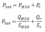
Where Qx is the gas load and Sx is the pump speed for each water vapor and residual gases. Quite often one knows the gas load QH2O of the water vapor from a residual gas analysis. Using that one can work out the expected water vapor pump speed and a prediction can be made has to how much the total pressure can be reduced.

In the case when a water pump is used as an appendage pump, meaning that it can be isolated by a gate valve, one must be aware that if there is a partial pressure of water vapor in the system and if the pump is isolated then the water pump speed reduced. The pressure of the system will increase accordingly. For example, suppose there are a cryopanel and a turbomolecular pump in parallel on the chamber the total pump speed for water will be

pump speeds.PNG

If one isolates the cryopanel, then one is only left with turbomolecular pump pumping on that water vapor. At the time that the cryopanel is isolated, there is a water vapor gas load at that particular time is H2O(t). Therefore the resulting pressure will rise accordingly depending on how much cryopanel water pump speed is loss.

This is important to understand, especially if the system engineer is interested in reducing the post maintenance recovery of a tool using water pumps. Many tools such as plasma systems cannot tolerate a water pump in the process environment therefore the water pump is put behind an isolation gate valve. The process engineer must understand that although the target recovery pressure may have been achieved with the use of a water pump that there is still a water gas load, H2O(t). The water pumping speed SH2O will be reduced to the level of the high vacuum pump and PH2O will increase according to the loss of water pump speed.

I hope that you find this helpful. More useful vacuum technology can be found in the book Understanding Modern Vacuum Technology.

What is a Watt Balance?

These are “exciting” times for meteorologist. In 2018, it is expected that all of the fundamental SI units will be defined, including the kilogram. Right now, a kilogram artifact sits in France. It is the kilogram which is agreed that will be the definition of the kilogram, period. So if it shifts by a microgram, the reference standards in the national laboratories will shift by a microgram. Wouldn’t it be better to have a definition of the kilogram based on fundamental constants of the universe rather than an artifact? That is what is going on right now.

First, take a look at this short video that describes a watt balance is and how it works. This will help you understand the video that follows.

watt balance diagram

And of course, there has to be some vacuum technology involved!

Watt Balance.PNG chamber.PNG

The NIST-4 watt balance has measured Planck’s constant to within 34 parts per billion, demonstrating that the high-tech scale is accurate enough to assist with 2018’s planned redefinition of the kilogram. The watt balance is shown sitting in the bottom half of its vacuum chamber (left) and with the vacuum dome installed (right).

Credit: J. L. Lee / NIST

YouTuber Veritasium takes us into the National Institute of Standards and Technology to see one of the American standards.


You can learn much more at the NIST Physical Measurement Laboratory site.
NIST CODATA 2010 wallet card.jpg

NIST CODATA 2010 wallet card 2.jpg

Training the Next Generation of Vacuum Technologists

I had the opportunity to talk with Del Smith of Normandale Community College in Bloomington, Minnesota last fall at the American Vacuum Society Symposium in Nashville, Tennessee. Del has put together a phenomenal set of accredited classes specifically to teach vacuum technology and thin film technology with the purpose of graduating qualified technicians.

In this video, Del presents the concept of vacuum technology to laypeople and discussed the importance of training qualified technicians. He points out that unlike mechanical, electrical or medical technicians, vacuum technicians are a relatively small group of individuals but are in high demand.

It is well worth watching this video as Del explains the importance that industry is placing on having trained individuals who understand in detail vacuum technology beyond just being able operate the equipment from recipes without understanding.

From the YouTube post:
“Published on Nov 9, 2016 From TVs to potato chip bags, “thin film” is used in myriad ways. Normandale Community College is helping to make it possible for you to use all of your current technology. It is the only community college in the country to offer an associate degree in vacuum and thin-film technology. Every electronic device uses thin film in some way and NCC is focused on the thin-film used in computer chips and computer hard drives. Del Smith is a graduate of the University of Minnesota, and has worked for high tech companies in the Twin Cities area his entire career. Del spent thirty years at Honey-well Aerospace, where he was the lead engineer in two different areas; the Thin Film Facility and the Vacuum Laboratory. Del was a member of the team that established the Vacuum and Thin Film program at NCC in the mid 1990s, and taught part time for a few years. The program was started at the request of several local companies who recognized the need for more educated technicians as the equipment they were using became more complex. Today, due to a three year $800,000 grant from the National Science Foundation, Del’s class reaches students not only in Bloomington, but as far away as Ireland through “telepresence” instruction. Join us to learn more about this technology and the ways our lives depend on it.”

I admire Del for the well thought out program and equipment he put together and his desire to to give back to the vacuum industry.


Out of print vacuum tube books

I was chewing on a problem with some tungsten cathodes in a pressure gauge. I knew that guys like Irving Langmuir had probably solved that problem a long time ago. After all, we have been putting incandescent tungsten in vacuum systems for more than a century. That started me on a search for old books.

Irving_Langmuir_and_Guglielmo_Marconi_in_lab.jpg

Langmuir (center) in 1922 in his lab at GE, showing radio pioneer Guglielmo Marconi (right) a new 20 kW triode tube. Wikipedia.org. Langmuir worked at General Electric from 1909–1950, where he advanced several basic fields of physics and chemistry, invented the gas-filled incandescent lamp, the hydrogen welding technique, and was awarded the 1932 Nobel Prize in Chemistry for his work in surface chemistry.

My search took me to an unassuming, yet interesting place; www.tubebooks.org. This is a vast collection of out of print materials that have been scanned into PDF format. I did find some juicy books for vacuum tube technology and got some great insights into the problems of the day.

The site’s heading proclaims, “Herein you will find a collection of vintage engineering texts, vacuum tube datasheets, and other obsolete information, presented free of charge and without annoying advertisements.”

How gas flows through a multi-lobe roughing pump with a blower

This video published by Pfeiffer Vacuum shows how gas flows from the inlet of a blower to the multi-stage roots pump and out the exhaust.

The purpose of mounting a blower (the top section of this pump) onto a multi-lobe roughing pump is that it dramatically increases the pumping speed and extends the lower pressure capability of the pump. Typically the multi-lobe pump will have a speed of 100 cubic meters per hour. Adding the blower can boost the pump speed to 600 cmh to 1000 cmh, depending on the model

A4 pump speeds.PNG

Source: A4 series data sheet. Pfeiffer Vacuum

These pumps can be robust enough to handle harsh processes. Like all harsh duty pumps, there is a nitrogen blow-by on the bearings to prevent process by-products from destroying them. Depending on the manufacturer, gas purges may be introduced into the various stages of the pump to help move corrosive material through. Manufactures will also run the pumps at elevated temperatures.

Pfeiffer Vacuum (Asslar, Germany) purchased the Adixen  (Anecy, France)  on 31 December 2010. This filled a gap that existed in Pfeiffer’s roughing pump portfolio. It also opened up markets for both companies.

Other companies that make multi-stage roots pumps are Edwards Vacuum, Kashiyama and Ebara.

You can learn more about roughing pumps in Understanding Modern Vacuum Technology.

AVS 64 in Tampa

AVS64_727x150

Preparations for the program of AVS 65 International Symposium and Exhibition are well underway. The deadline for the submission of was the 1 May, 2017. That means that those of us who are on the Program Committee of the Vacuum Technology Division are reading through the abstracts and putting together the program.

I have just been through the 57 abstracts for the VTD program and I am impressed. We will be getting briefed on some cutting edge technologies. There is a new paradigm in pressure technology discussed. NIST is moving over from mercury manometers to photonic based pressure standards.

Tri Alpha Energy will be giving a talk on the progress of their latest fusion reactor. They have some very stringent vacuum requirements and are using chemisorption surfaces to pump H2 along with cryogenic surfaces.

There will be several discussions about vacuum generation in high energy physics experiments in Japan, the UK, Germany and the US.

Paul Arnold of MKS/Granville-Phillips will give an invited talk as part of the AVS History Committee endeavor to preserve our technical heritage. He will discuss the Electro-Ion pump developed in the 1960s. This was a complex UHV pump that combined cutting edge technologies in one package; a titanium sublimation pump with a triode pump.

There will be discussion about handling EUV exposure systems, vacuum systems to improve storage batteries, process development for new lighting technologies and much, much more.